Chevrolet Cobalt Service & Repair Manual: Battery Cable, Replace
Ground Cable
Battery To Battery Tray
| Caution: Unless directed otherwise,
the ignition and start switch must be in the OFF or LOCK position, and all
electrical loads must be OFF before servicing any electrical component.
Disconnect the battery ground to prevent an electrical spark should a tool
or equipment come in contact with an exposed electrical terminal. Failure
to follow these precautions may result in personal injury and/or damage
to the vehicle or its components. |
| For Vehicles equipped with OnStar®
with Back-Up Battery: The Back-Up Battery is a redundant power supply to
allow limited OnStar® functionality in the event of a main vehicle battery
power disruption to the VCIM (OnStar® module). Do not disconnect the main
vehicle battery or remove the OnStar® fuse with the ignition key in any
position other than OFF. Retained accessory power should be allowed to time
out or be disabled (simply opening the driver door should disable retained
accessory power) before disconnecting power. Disconnecting power to the
OnStar® module in any way while the ignition is ON, or with retained accessory
power activated, may cause activation of the OnStar® Back-Up Battery system
and will discharge and permanently damage the Back-Up Battery. Once the
Back-Up Battery is activated, it will stay on until it has completely discharged.
The Back-Up Battery is not rechargeable and once activated, the Back-Up
Battery must be replaced. |
| Always use replacement cables
that are of the same type, diameter and length of the cables that are being
replaced. |
| Always route the replacement cable
the same way as the original cable. |
| 1. |
Disconnect battery ground cable from
battery. |
| 2. |
Disconnect body harness electrical
connector (7) from battery current sensor (6), Fig. 1. |
| 3. |
Remove battery ground cable ground
bolt (4), Fig. 1. |
| 4. |
Separate battery ground cable terminal
(5) from battery support, Fig. 1. |
| 5. |
Remove battery ground cable (3),
Fig. 1. |
| 6. |
Reverse procedure to install, noting
following: |
| |
a. |
Ensure anti-rotation tab on terminal
(5) is correctly located, Fig. 1. |
| |
b. |
Torque battery ground cable
ground bolt (4) to 13 ft. lbs., Fig. 1. |
|
Engine To Chassis
| Caution: Unless directed otherwise,
the ignition and start switch must be in the OFF or LOCK position, and all
electrical loads must be OFF before servicing any electrical component.
Disconnect the battery ground to prevent an electrical spark should a tool
or equipment come in contact with an exposed electrical terminal. Failure
to follow these precautions may result in personal injury and/or damage
to the vehicle or its components. |
| For Vehicles equipped with OnStar®
with Back-Up Battery: The Back-Up Battery is a redundant power supply to
allow limited OnStar® functionality in the event of a main vehicle battery
power disruption to the VCIM (OnStar® module). Do not disconnect the main
vehicle battery or remove the OnStar® fuse with the ignition key in any
position other than OFF. Retained accessory power should be allowed to time
out or be disabled (simply opening the driver door should disable retained
accessory power) before disconnecting power. Disconnecting power to the
OnStar® module in any way while the ignition is ON, or with retained accessory
power activated, may cause activation of the OnStar® Back-Up Battery system
and will discharge and permanently damage the Back-Up Battery. Once the
Back-Up Battery is activated, it will stay on until it has completely discharged.
The Back-Up Battery is not rechargeable and once activated, the Back-Up
Battery must be replaced. |
| Always use replacement cables
that are of the same type, diameter and length of the cables that are being
replaced. |
| Always route the replacement cable
the same way as the original cable. |
| 1. |
Disconnect battery ground cable from
battery. |
| 2. |
On models with automatic transaxle,
proceed as follows: |
| |
a. |
Remove engine harness ground nut (4),
Fig. 2. |
| |
b. |
Remove engine harness ground terminal
(3) from stud (1), Fig. 2. |
| |
c. |
Remove battery ground cable ground
terminal (2) from stud (1), Fig. 2. |
| 3. |
On models with manual transaxle,
proceed as follows: |
| |
a. |
Raise and support vehicle using suitable
lift. |
| |
b. |
Remove engine harness ground nut (1),
Fig. 3. |
| |
c. |
Remove engine harness ground terminal
(2) from stud (3), Fig. 3. |
| |
d. |
Remove ground cable stud (3), Fig.
3. |
| |
e. |
Separate battery ground cable ground
terminal (4) from engine block, Fig. 3. |
| 4. |
On all models, remove lefthand
headlamp. |
| 5. |
Remove battery ground cable ground
nut from stud on side rail, through lefthand headlamp opening,
Fig. 4. |
| 6. |
Remove battery ground cable ground
terminal from stud, Fig. 4. |
| 7. |
Cut open tape on positive/ground battery
cable conduit (1), and remove old tape from conduit, Fig.
5. |
| 8. |
Separate battery ground cable (2) from
positive cable (1) and remove ground cable from vehicle, Fig.
6. |
| 9. |
Reverse procedure to install, noting
following: |
| |
a. |
Torque battery ground cable
ground nut to stud on side rail to 15 ft. lbs. |
| |
b. |
On models with manual transaxle,torque
ground cable stud to 18 ft. lbs. |
| |
c. |
On all models,torque
engine harness ground nut to 13 ft. lbs. |
|
Positive Cable
Battery To Junction Block
| Caution: Unless directed otherwise,
the ignition and start switch must be in the OFF or LOCK position, and all
electrical loads must be OFF before servicing any electrical component.
Disconnect the battery ground to prevent an electrical spark should a tool
or equipment come in contact with an exposed electrical terminal. Failure
to follow these precautions may result in personal injury and/or damage
to the vehicle or its components. |
| For Vehicles equipped with OnStar®
with Back-Up Battery: The Back-Up Battery is a redundant power supply to
allow limited OnStar® functionality in the event of a main vehicle battery
power disruption to the VCIM (OnStar® module). Do not disconnect the main
vehicle battery or remove the OnStar® fuse with the ignition key in any
position other than OFF. Retained accessory power should be allowed to time
out or be disabled (simply opening the driver door should disable retained
accessory power) before disconnecting power. Disconnecting power to the
OnStar® module in any way while the ignition is ON, or with retained accessory
power activated, may cause activation of the OnStar® Back-Up Battery system
and will discharge and permanently damage the Back-Up Battery. Once the
Back-Up Battery is activated, it will stay on until it has completely discharged.
The Back-Up Battery is not rechargeable and once activated, the Back-Up
Battery must be replaced. |
| Always use replacement cables
that are of the same type, diameter and length of the cables that are being
replaced. |
| Always route the replacement cable
the same way as the original cable. |
| 1. |
Disconnect battery ground cable from
battery. |
| 2. |
Reposition carpet, but do not remove
console. |
| 3. |
Open positive battery cable (1) cover,
Fig. 1. |
| 4. |
Loosen positive battery cable nut. |
| 5. |
Remove positive battery cable (1) from
battery, Fig. 1. |
| 6. |
Disconnect positive battery cable electrical
connector (9) from body harness electrical connector (8), Fig.
1. |
| 7. |
Remove positive battery cable clips
(1) from weld studs, from inside vehicle, Fig. 7. |
| 8. |
Remove positive battery cable clip
(2) from floor pan, Fig. 7. |
| 9. |
Remove positive battery cable clip
(2) from latch bar, Fig. 8. |
| 10. |
Unfold body clip tabs and remove positive
battery cable from body clip (3), Fig. 8. |
| 11. |
Remove positive battery cable clips
(3) from weld studs, Fig. 8. |
| 12. |
Remove positive battery cable clip
(4) from floor pan, Fig. 8. |
| 13. |
Remove positive battery cable from
body wiring harness clips (1), Fig. 9. |
| 14. |
Remove positive battery cable clip
(2) from weld stud, Fig. 10. |
| 15. |
Remove positive battery cable from
body wiring harness clips (3), Fig. 10. |
| 16. |
Unseat grommet (1) from front of dash,
Fig. 10. |
| 17. |
Remove junction block cover. |
| 18. |
Remove junction block nut (1), Fig.
11. |
| 19. |
Remove positive battery cable terminal
(2) from junction block stud, Fig. 11. |
| 20. |
Remove positive battery cable (3) from
body wiring harness clip (2), Fig. 12. |
| 21. |
Remove positive battery cable clip
(1) from junction block, Fig. 12. |
| 22. |
Remove positive battery cable from
under junction block. |
| 23. |
Route positive battery cable through
hole in front of dash. |
| 24. |
Remove positive battery cable from
inside vehicle. |
| 25. |
Reverse procedure to install, noting
following: |
| |
a. |
Torque junction block nut to
13 ft. lbs. |
| |
b. |
Torque positive battery cable
nut to 13 ft. lbs. |
|
Junction Block To Starter
| Caution: Unless directed otherwise,
the ignition and start switch must be in the OFF or LOCK position, and all
electrical loads must be OFF before servicing any electrical component.
Disconnect the battery ground to prevent an electrical spark should a tool
or equipment come in contact with an exposed electrical terminal. Failure
to follow these precautions may result in personal injury and/or damage
to the vehicle or its components. |
| For Vehicles equipped with OnStar®
with Back-Up Battery: The Back-Up Battery is a redundant power supply to
allow limited OnStar® functionality in the event of a main vehicle battery
power disruption to the VCIM (OnStar® module). Do not disconnect the main
vehicle battery or remove the OnStar® fuse with the ignition key in any
position other than OFF. Retained accessory power should be allowed to time
out or be disabled (simply opening the driver door should disable retained
accessory power) before disconnecting power. Disconnecting power to the
OnStar® module in any way while the ignition is ON, or with retained accessory
power activated, may cause activation of the OnStar® Back-Up Battery system
and will discharge and permanently damage the Back-Up Battery. Once the
Back-Up Battery is activated, it will stay on until it has completely discharged.
The Back-Up Battery is not rechargeable and once activated, the Back-Up
Battery must be replaced. |
| Always use replacement cables
that are of the same type, diameter and length of the cables that are being
replaced. |
| Always route the replacement cable
the same way as the original cable. |
| 1. |
Disconnect battery ground cable from
battery. |
| 2. |
Remove junction block cover. |
| 3. |
Remove junction block nut (1), Fig.
11. |
| 4. |
Remove positive battery cable terminal
(2) from junction block stud, Fig. 11. |
| 5. |
Remove positive battery cable clip
(3) from engine control module (ECM) bracket, Fig. 11. |
| 6. |
Raise and support vehicle using suitable
lift. |
| 7. |
Remove starter solenoid terminal nut
(5), Fig. 13. |
| 8. |
Remove positive battery cable terminal
(4) from starter solenoid, Fig. 13. |
| 9. |
Cut open tape on positive/ground battery
cable conduit (1), and remove old tape from conduit, Fig.
5. |
| 10. |
Separate positive battery cable (1)
from ground cable (2) and remove positive battery cable from vehicle,
Fig. 6. |
| 11. |
Reverse procedure to install, noting
following: |
| |
a. |
Torque starter solenoid terminal
nut to 13 ft. lbs. |
| |
b. |
Torque junction block nut to
13 ft. lbs. |
|
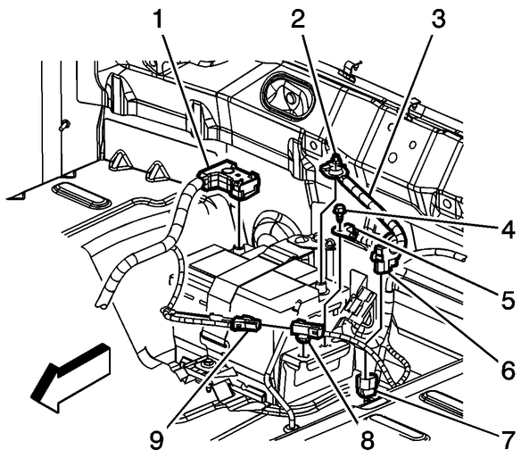
Fig. 1 Battery ground cable removal from battery & tray
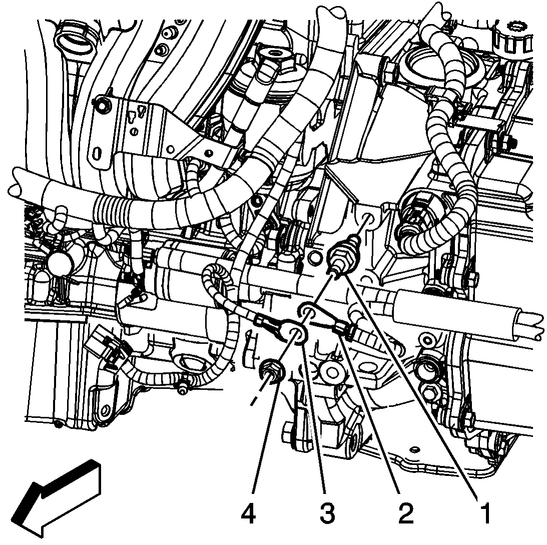
Fig. 2 Engine harness & ground cable removal from stud. Automatic transaxle
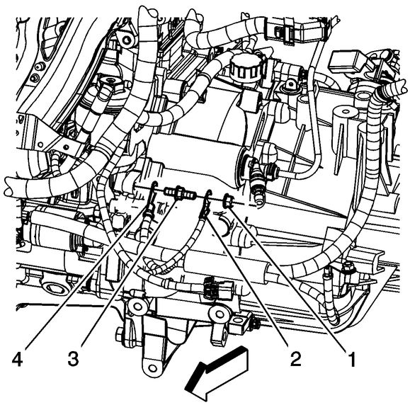
Fig. 3 Engine harness & ground cable removal from stud. Manual transaxle
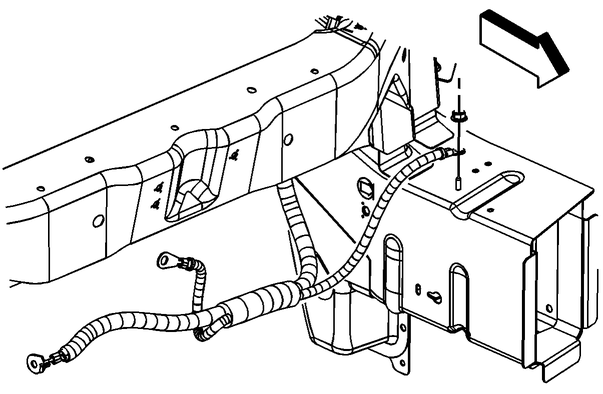
Fig. 4 Battery ground cable removal from side rail
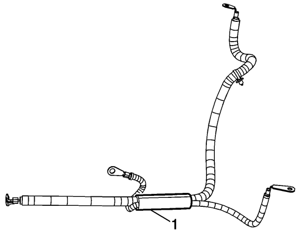
Fig. 5 Positive/ground battery cable conduit tape location
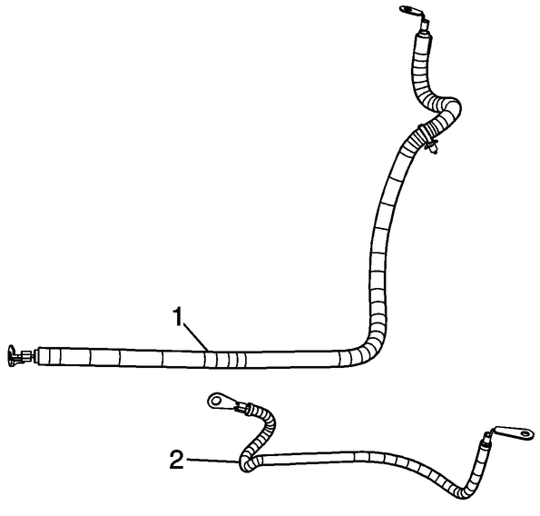
Fig. 6 Exploded view of battery positive & ground cables
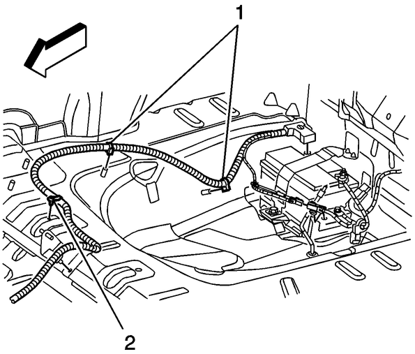
Fig. 7 Positive battery cable removal from floor pan weld studs
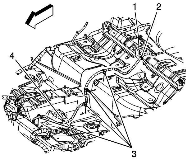
Fig. 8 Positive battery cable removal from body clip & floor pan
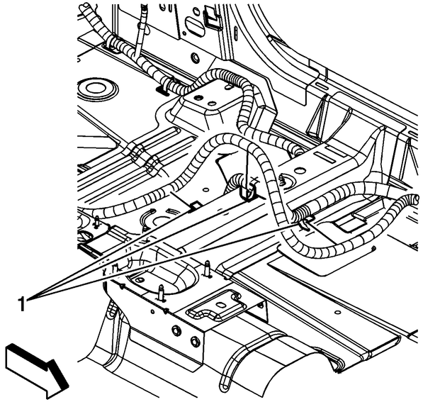
Fig. 9 Positive battery cable removal from body harness clips
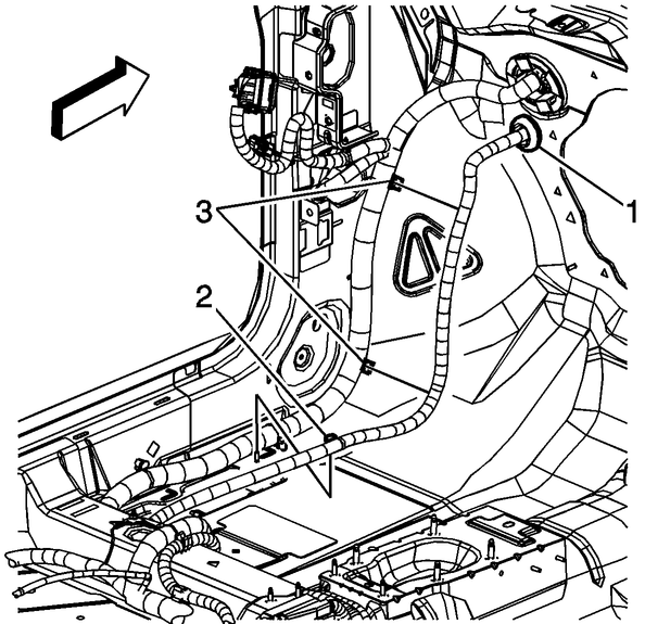
Fig. 10 Positive battery cable removal from front of dash
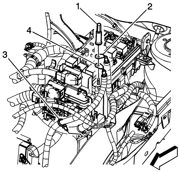
Fig. 11 Positive battery cable terminal removal from junction block
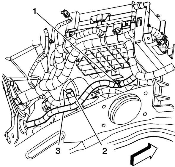
Fig. 12 Positive battery cable removal from junction block
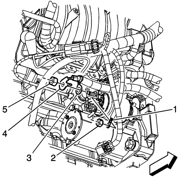
Fig. 13 Positive battery cable removal from starter
Caution: Use protective gloves
and eye protection.
Caution: Perform procedure
in a well ventilated area.
Caution: Refer to cautions
and warnings listed on ...
1.
Raise and support the vehicle.
2.
Place a drain pan under the oil drain
plug.
3.
Remove the oil pan drain ...
See also:
Chevrolet Cobalt Owners Manual. How to Wear Safety Belts Properly
This section is only for people of adult size.
Be aware that there are special things to know about
safety belts and children. And there are different rules
for smaller children and infants. If a child will be riding in
the vehicle, see Older Children or Infants
and Young Children. Follow those ...


 Battery Cable Terminal End Service
 Engine Oil Filter R & R