Chevrolet Cobalt Service & Repair Manual: Adjustments
Brake Pedal
| 1. |
With ignition OFF and brakes cool,
apply brakes three or four times, or until brake pedal becomes firm,
in order to deplete brake booster power reserve. |
| 2. |
Adjust steering wheel angle to highest
tilt position and lock wheel in place. |
| 3. |
Install brake pedal effort gauge tool
No. J 28662, or equivalent, to brake pedal. |
| 4. |
Release parking brake and start engine. |
| 5. |
With engine running at idle speed,
measure and record distance from brake pedal to rim of steering
wheel. |
| 6. |
Slowly apply and maintain brakes with
66 lbs. of force to brake pedal. |
| 7. |
While maintaining 66 lbs. of force
to brake pedal, measure and record distance from same point on brake
pedal to same point on rim of steering wheel. |
| 9. |
Subtract initial unapplied measurement
from applied measurement in order to obtain brake pedal travel distance.
Specification Maximum brake pedal travel, measured with 66 lbs.
of force to brake pedal, engine ON, and brakes cool, is 2.8 inches. |
| 11. |
Remove brake pedal effort gauge tool
No. J 28662, or equivalent, from brake pedal. |
| 12. |
If brake pedal height and travel require
adjustment, turn pedal pushrod and then tighten pushrod lock nut. |
|
Master Cylinder Pushrod
| Proper adjustment of the master
cylinder pushrod is required to ensure proper operation of the power brake
system. A pushrod that is too long will cause the master cylinder piston
to close off the compensating port, preventing hydraulic pressure from being
released and resulting in brake drag. A pushrod that is too short will cause
excessive brake pedal travel and cause groaning noises to come from the
booster when the brakes are applied. A properly adjusted pushrod that remains
assembled to the booster with which it was matched during production should
not require service adjustment. However, if the booster, master cylinder
or pushrod are serviced, the pushrod may require adjustment. |
| There are two methods that can
be used to inspect for proper pushrod length and installation. These are
the gauge method and air method. Usually, if the power unit pushrod requires
adjustment, use the power unit repair kit gauge. The gauge measures from
the end of the pushrod to the power unit shell. |
Gauge Method
Tandem Diaphragm Type
| The master cylinder pushrod length
is fixed and is usually only inspected after the unit has been overhauled.
This procedure can be performed with the unit removed from the vehicle if
a suitable vacuum source is available. |
| 1. |
Assemble booster unit and install pushrod.
Ensure pushrod is fully seated. |
| 2. |
Apply 20 inches or maximum engine vacuum
to booster. |
| 3. |
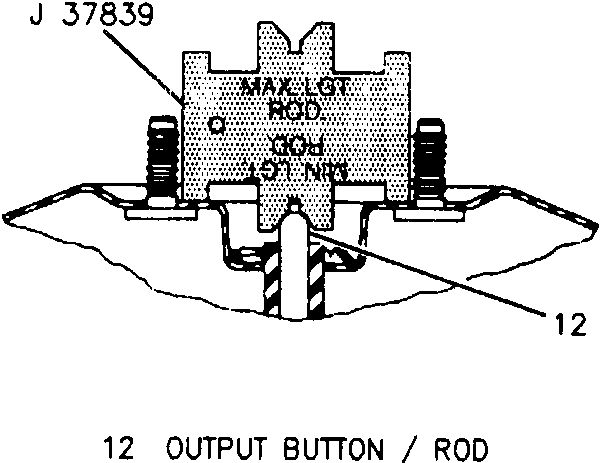
Position gauge tool No. J-37839, or
equivalent, over pushrod, Fig. 1. |
| 4. |
Replace booster if output button length
is not within gauge limits. |
| 5. |
Install power unit and inspect adjustment. |
| 6. |
Ensure master cylinder compensating
port is open with engine running and brake pedal released. |
|
Air Method
| 1. |
Ensure master cylinder mounting nuts
are tight. |
| 2. |
Remove master cylinder filler cap. |
| 3. |
With brake released, force compressed
air into hydraulic outlet of master cylinder. Regulate air pressure
to value of approximately 5 psi to prevent spraying brake fluid
from master cylinder. |
| 4. |
If air passes through compensating
port, which is smaller of two holes in bottom of master cylinder
reservoir, adjustment is satisfactory. |
| 5. |
If air does not flow through compensating
port, adjust pushrod as required, either by means of adjustment
screw (if provided) or by adding shims between master cylinder and
power unit shell until air flows freely. |
| 6. |
Connect brake lines and bleed system. |
|

Fig. 1 Master cylinder measurement. Tandem diaphragm type
AC-Delco Tandem Diaphragm Type
This unit utilizes a vacuum power
chamber, consisting of a front and rear shell, housing divider, front and
rear diaphragm, plate assemblies, hydraulic p ...
Chevrolet Cobalt Owners Manual
Chevrolet Cobalt Service Manual

 Description
